GCSE
Computer Science
-
Introduction to GCSE Computer Science -
1.1 Systems Architecture -
1.2 Memory and Storage -
1.3 Computer Networks, Connections and Protocols -
1.4 Network Security -
1.5 Systems Software -
1.6 Ethical, Legal, Cultural and Environmental Impacts of Digital Technology -
2.1 Algorithms -
2.2 Programming Fundamentals -
2.3 Producing Robust Programs -
2.4 Boolean Logic -
2.5 Programming Languages and Integrated Development Environments
1. Computer Systems
In this lesson, we will learn about simple logic diagrams, truth tables, and how to combine Boolean operators using AND, OR, and NOT. We'll exclusively use variables A and B in the diagrams to make the concepts clear.
Simple Logic Diagrams using AND, OR, and NOT
Boolean Logic involves three primary logical operators: AND (∧), OR (∨), and NOT (¬). These operators connect two binary input values (often represented by variables A and B) and produce an output value.
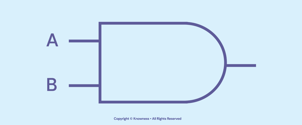
AND Operator (∧)
The AND operator requires both input values (A and B) to be TRUE (1) to produce a TRUE (1) output. If either A or B is FALSE (0), the output will be FALSE (0).
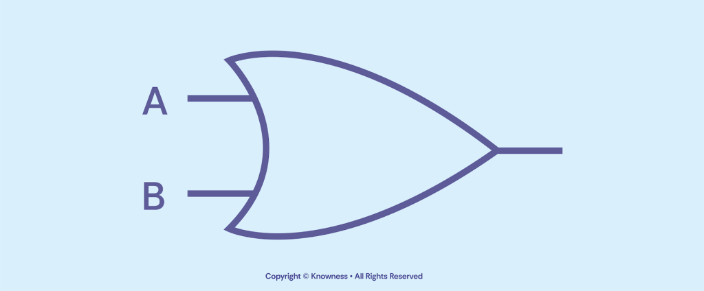
OR Operator (∨)
The OR operator produces a TRUE (1) output if at least one of the input values (A or B) is TRUE (1). It results in a FALSE (0) output only when both A and B are FALSE (0).
NOT Operator (¬)
The NOT operator negates the input value (outputs the opposite of the input). If the input A is TRUE (1), NOT produces FALSE (0), and vice versa.

Continue the lesson
This section is available to learners with course access. Continue learning with Knowness to unlock the full explanation, examples, revision tools, and progress tracking.
The remaining lesson content includes further guided explanation, important learning points, and supporting interactive material designed to help you understand and revise this topic.
Unlock this topic to view the full activity, worked examples, common mistakes, and additional revision support.
More content available
Knowness lessons are structured to build understanding step by step. Create an account or upgrade your access to continue from this point.
This preview does not include the hidden lesson text, answers, explanations, or embedded interactions.
Continue learning with Knowness
Sign up to access the full lesson, predicted grades, revision tools, progress tracking, and more.
Create a free accountBoolean Logic
- Boolean logic uses three core operators: AND (∧), OR (∨), and NOT (¬) to control logical flow in programs.
- AND (∧) returns TRUE (1) only if both inputs are TRUE.
- OR (∨) returns TRUE (1) if at least one input is TRUE.
- NOT (¬) inverts the input: TRUE becomes FALSE, and FALSE becomes TRUE.
- Truth tables show all possible combinations of input values and the corresponding output for a Boolean expression.
- Boolean operators can be combined to form more complex logic (e.g. A AND NOT B, A OR (B AND NOT C)).
- A truth table with n inputs has 2ⁿ rows—e.g., 8 rows for 3 variables.
- Logic diagrams use visual symbols to represent logic gates and how inputs are processed.